
1 / 7 · Click to enlarge
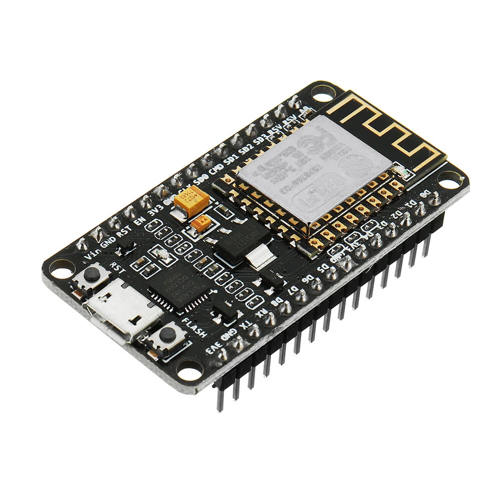
TTGO T-OI ESP8266 Chip Rechargeable 16340 Battery Holder Development Board
 T-OI ESP8266 Development Board
 WS2812 RGB Expansion Board
The TTGO T-OI ESP8266 Chip Rechargeable 16340 Battery Holder Development Board is a mid-range battery protection module designed for everyday users. It features One Package Weight: 0.02kgs / 0.05lb and One Package Size: 15cm * 10cm * 1cm / 5.91inch * 3.94inch * 0.39inch.
Available Offers
Free Delivery on this order. No minimum order value.
15-Day Easy Returns — hassle-free return & full refund.
Secure Payment — 100% safe checkout with UPI, Cards & Net Banking.
Available Offers
5% Cashback
Pay with UPI & get 5% cashback (up to ₹50) via Razorpay
No-Cost EMI
Available on select bank cards at checkout. 0% interest for 3 months.
Free Shipping
Free delivery on all orders. No minimum order value.
Cash on Delivery
COD available on orders up to ₹5,000 across India.
Quick Specs
Ideal For
About This Product
The TTGO T-OI ESP8266 Chip Rechargeable 16340 Battery Holder Development Board is a mid-range battery protection module designed for everyday users. It delivers reliable performance at an accessible price.
Key Specifications
- One Package Weight: 0.02kgs / 0.05lb
- One Package Size: 15cm * 10cm * 1cm / 5.91inch * 3.94inch * 0.39inch
- Best Sellers Rank (Consumer Electronics): #5689
- Best Sellers Rank (Consumer Electronics > DIY Parts & Components ): #158
- Best Sellers Rank (Consumer Electronics > DIY Parts & Components > Module): #35
Why Buy from Elecvora?
Elecvora sources this product directly, cutting out multiple middlemen. Every order includes free shipping, a 15-day return policy, and secure payment via Razorpay.
Features 1. Added 16340 electrical socket to the ordinary development board, which can use the corresponding rechargeable 16340 battery to power the system, which is convenient, beautiful and practical. 2. The product is compact and the size design extends the size design of this battery holder. 3. All IO ports are reserved from both sides, compatible with the distance between MINI D1 extended version and breadboard. Grove interface is reserved at the same time, compatible with Grove interface module, and T-Watch sensor module (T-Watch special connection cable needs to be connected). 4. We will design more convenient expansion modules to match the motherboard to facilitate the realization of various ideas for learners. Hardware Specifications 1. Chipset: ESP8266EX 2. USB to TTL: CH340K 3. Charging chip: TP4054 4. FLASH: 4MB 5. Size: 43.96x25.63x20.80mm 6. Weight:7.87g Power Supply 1. Battery: 16340 3.7V rechargeable lithium battery(not included) 2. Battery switch:Yes 3. USB: Micro USB Wi-Fi 1. External antenna mount: With IPEX antenna mount 2. WIFI antenna: Ceramic antenna